Hardware Interfaces
Power Input
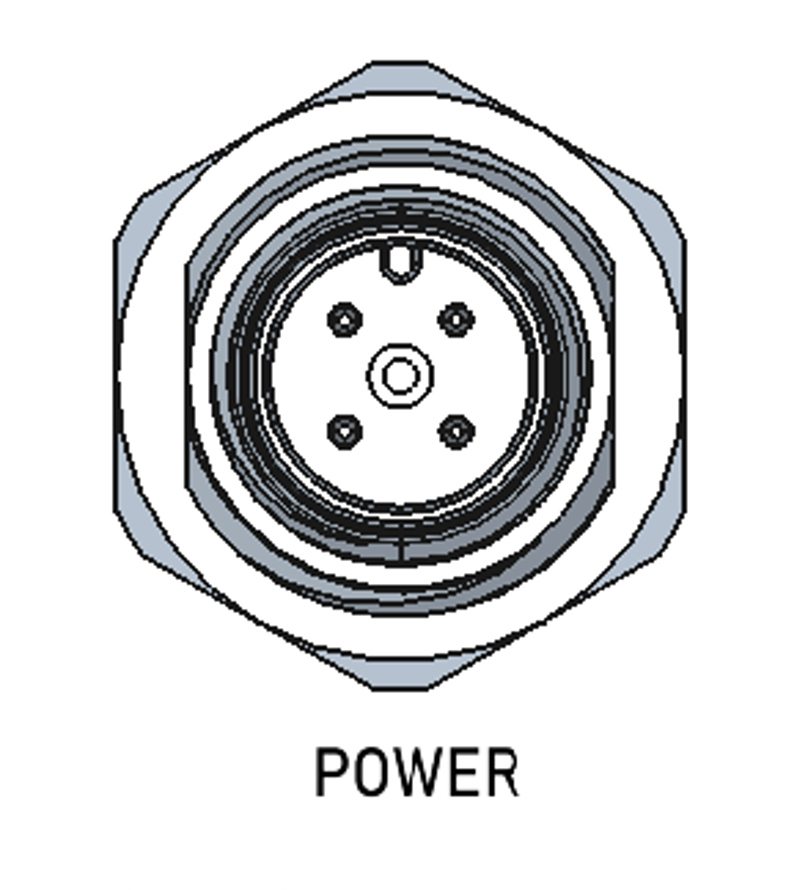
The SIO07 is supplied via an M12-4pin-A-coded (male) connector. The following picture shows the power supply connector location.
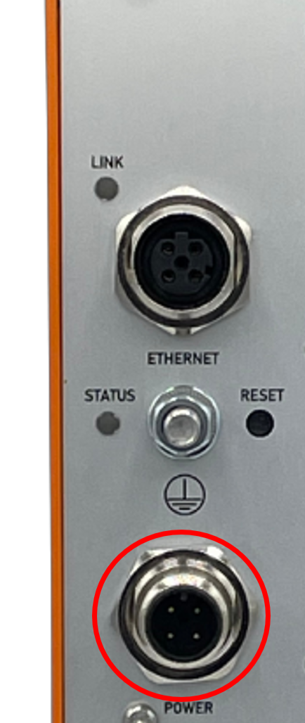
Pinning of power supply connector:
| Pin | Signal Designator | Signal Description |
|---|---|---|
| 1 | Vin+ | Pos. supply voltage |
| 2 | N/C | Not connected |
| 3 | Vin- | Neg. supply voltage |
| 4 | Vin- | Neg. supply voltage |
Ethernet Interface
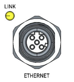
The SIO07 provides a 100MBit/s Ethernet interface via an M12-4pin-D-coded (female) connector.
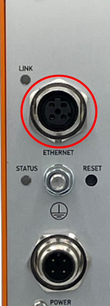
Pinning of Ethernet connector:
| Pin | Signal Designator | Signal Description |
|---|---|---|
| 1 | TD+ | Transmit (Diff +) |
| 2 | RD+ | Receive (Diff +) |
| 3 | TD- | Transmit (Diff -) |
| 4 | RD- | Receive (Diff -) |
Serial Interface (COM Port)
The SIO07 is supplied via an 9-pin D-Sub (female) connector for Serial Interface.
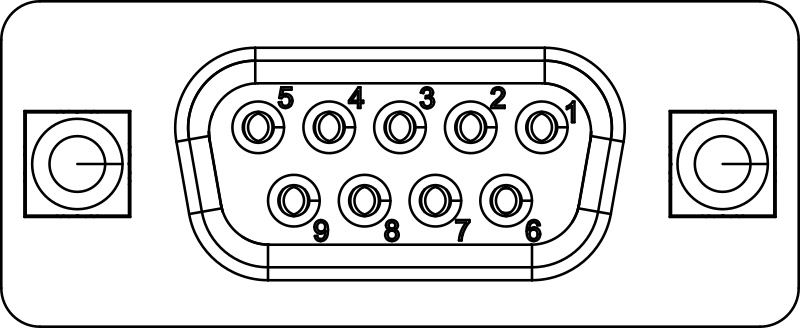
Pin functionality as viewed from SIO07:
| Pin | Symbol | Description |
|---|---|---|
| 1 | RS485_TX+ | RS485 positive transmit line |
| 2 | RS232_TXD | RS232 transmit line |
| 3 | RS232_RXD | RS232 receive line |
| 4 | RS485_RX+ | RS485 positive receive line |
| 5 | GND | Ground (isolated from other interfaces) |
| 6 | RS485_TX- | RS485 negative transmit line |
| 7 | RS232_CTS | RS232 clear to send |
| 8 | RS232_RTS | RS232 request to send |
| 9 | RS485_RX- | RS485 negative receive line |
Bitbus Interface
The SIO07 is supplied via one 9-pin D-Sub (male) and one 9-pin D-Sub (female) connector for Bitbus Interface
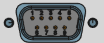
Pin functionality as viewed from SIO07:
| Pin | Signal Designator | Signal Description |
|---|---|---|
| 1 | NC | not connected |
| 2 | NC | not connected |
| 3 | DATA- | negative bitbus data signal |
| 4 | RESERVED | do not connect |
| 5 | GND | Ground (isolated from other interfaces) |
| 6 | NC | not connected |
| 7 | NC | not connected |
| 8 | DATA+ | positive bitbus data signal |
| 9 | RESERVED | do not connect |
Service Interfaces
Service Console Interface
The SIO07 provides a USB-C service interface on the side, which is available when opening the left sidewall:
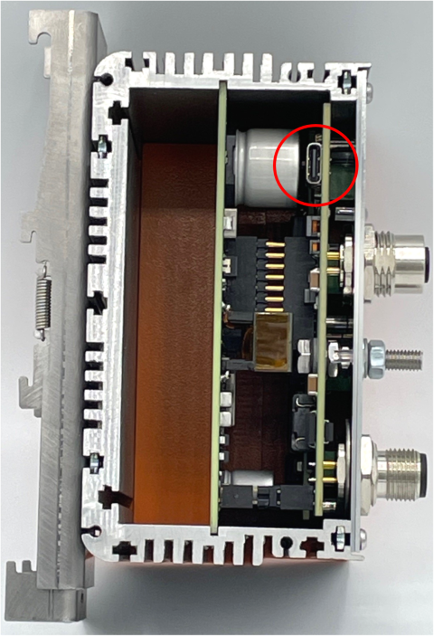
It provides a serial console interface (115200 8N1) for service and configuration purposes.
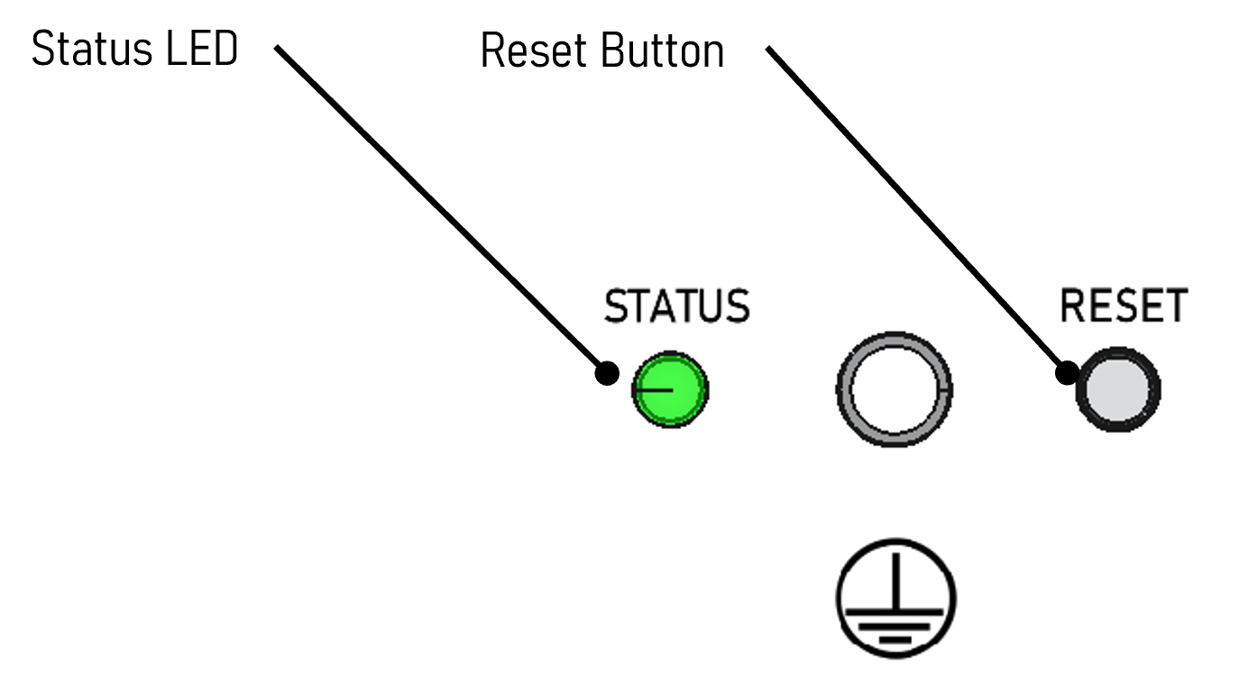
Reset Button
The SIO07 provides a front-accessible reset button:
Warning
In firmware version 1.0.1 and earlier, the reset button has no function.
A short activation (>1s, but <5s) of RESET_BUTTON restarts the device without changing current configuration.
A long activation (>10s) of RESET_BUTTON forces factory configuration of the device and restarts it. The STATUS LED will flash RED/YELLOW when factory state has been applied.
A “factory reset” sets the following parameters to default values:
- Configuration data (Such as static IP address)
Firmware and hardware inventory data are kept intact.
Status LED
The SIO07 provides one multicolor status LED on the front:
The STATUS LED indicates the current status of the device:
- OFF: Device is powered off or has not yet finished booting
- RED: Device startup failed
- GREEN: Device startup successful
Ethernet Status LED
The SIO07 provides one Ethernet LED on the front:

Ethernet status LED functionality:
| Color | Functionality |
|---|---|
| yellow | Link up |
| brighter yellow | Activity |
Bitbus LEDs
The SIO07 provides 4 LEDs for the Bitbus function. Currently, only two of them are used:
- Leftmost LED: Indicates Bitbus I/O Board has been started successfully (green)
- Second LED from left: Indicates Bitbus inactive (yellow) or active (blue) state