Install Tracelet
Install Tracelet and measure mounting parameters
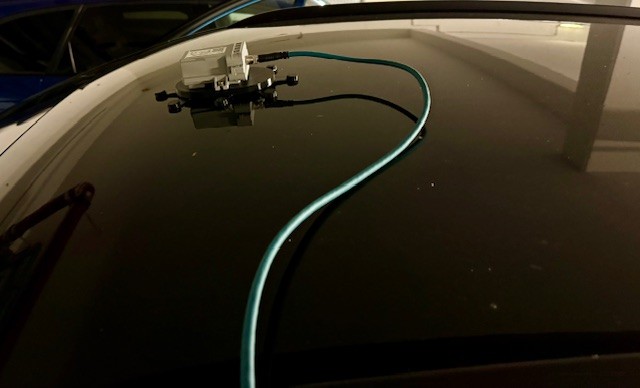
Install the Tracelet on the roof of the vehicle, using the provided base plate and the magnets.
- Ideally, left/right centered. If not installed in the middle, measure the distance to the vehicle centerline and write it down
- Ideally, yaw angle of 0, i.e. in parallel to the floor. If not, measure the yaw angle and write it down
- The cable outlet of the SIO02 must point to the vehicle rear
- Measure the distances between SIO02 center and the vehicle rotation point (rear axes of vehicle)/floor and write it down
- Measure the height of the Tracelet above ground level and write it down
Mounting parameters for Busses/Cars
For busses and cars, the vehicle rotation point (VRP) is the rear axle.
In case the tracelet is not installed in the left/right center of the vehicle, the Y-offset must be taken into account. Use positive values if the Tracelet is right to the center.

Mounting parameters for Trams
For trams, the vehicle rotation point (VRP) is the center between the bogies. For Y-Offset, the same rules apply as for busses.

Connect the Tracelet
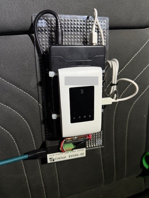
Place the plate with the power bank and router inside the vehicle.
Connect cable between the EVU04 adapter to the Tracelet.
Connecting the Wheeltick Signal
For dead reckoning, the tracelet must be connected to the wheeltick signal of the vehicle.
The wheeltick signal is a signal that is generated by the vehicle and reflects the distance traveled by the vehicle. The wheeltick signal is used to correct the GNSS and UWB positioning, especially in cases where the radio signal is weak or not available.
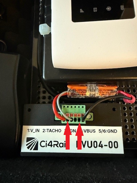
The wheeltick signal is connected to the EVU04 adapter on the WT pin. Furthermore, you must connect the adapter’s GND pin to the vehicle ground. The signal should have a voltage of >=4.8V (max 36V) when high and <=2.2V when low.
The tracelet firmware and configuration must fit to the wheeltick rate. It is usually specified in Ticks/km.
NOTE: The current tracelet firmware has a fixed wheeltick rate. To change the wheeltick rate, a different firmware must be flashed. The default wheeltick rate is 4000 Ticks/km. If you need a different rate, please contact us.
Using an OBD adapter as wheeltick source
If you want to test in a car and you can’t connect the wheeltick signal directly, you may use an OBD (onboard diagnostic adapter) to simulate the wheeltick signal. Such adapters regenerate the wheeltick signal from the vehicle’s speed information on the CANbus. One example can be found here. It has provides a wheeltick rate of 2500 Ticks/km. Please note that this specific adapter does not work with electric vehicles.