SIO03 Detailed Description
Features
- Seamless positioning from various sensor sources; < 1m accuracy
- UWB receiver IEEE 802.15.4-2015;
- GNSS/RTK multiband GNSS receiver
- Inertial Measurement Unit (IMU)
- Speed Pulse Signal according to IEC 16844-2
- 100MBit/s Ethernet, PoE PD class 1
- Alt. power input 9…36V DC (12/24V nom.); Ignition
- USB service interface
- Monitoring and remote maintenance (e.g. OTA update of firmware)
- Designed for use in Rail (EN 50155) and Buses (E-Mark)
Introduction
The UWB/RTK precise positioning module SIO03 is a member of the KYT Sensor family by Ci4Rail and can work as a standalone device as well as in combination with ModuCop MEC0x.
For highly precise positioning in public transport and rail car depots, stations, tunnels etc. or even indoor, a single sensor source is not sufficient. To provide precise localization, SIO03 combines the technologies UWB (ultra wide band), GNSS/RTK (Real-Time-Kinematik) and additional speed pulse input signal.
Whereas UWB works indoors using a cost sensitive satlet infrastructure, the GNSS/RTK technology provides high precision positioning information without additional infrastructure outdoors. The speed pulse input signal supports identification of distance traveled and movement direction. Specific movement models within an IMU (Inertial Measurement Unit) allow smooth seamless real-time positioning.
The positioning information is transferred to in-vehicle subsystems via Ethernet interface. The SIO03 product represents the vehicle component and does not cover stationary equipment like UWB satlets.
Detailed Technical Specification
| Feature | Value | ||
|---|---|---|---|
| Interfaces | |||
| Communication Interface | 100MBit/s Ethernet via M12 D-Coded | ||
| Service Interface | USB 2.0 via M12 8p A-Coded | ||
| Positioning Indoor | UWB IEEE 802.15.4-2015 | ||
| Positioning Outdoor | Multi-band GNSS/RTK | ||
| GPS/QZSS (L1C/A L2C) | |||
| GLONASS (L1OF L2OF) | |||
| Galileo (E1B/C E5b) | |||
| BeiDou (B1I B2I) | |||
| Position accuracy | localization values have an accuracy of < 1m for 95% of the reported values | ||
| Speed Pulse Signal | acc. to IEC 16844-2 (input high: 4,8V; input low: 2,2V) | ||
| Ignition | On State: Input high: 5,2 V (min) or open | ||
| Standby State (after delay ~3 sec): Input low: 3,6 V (max) | |||
| Maintenance | |||
| Firmware update | Via USB, LAN | ||
| Management | Via io4edge protocol, see io4edge protocol | ||
| Electrical | |||
| Power Supply | Power-over-Ethernet (PoE PD) class 1 | ||
| 12V, 24V (nom.) acc. to ISO 7637-2:2011 via M12 8p A-Coded | |||
| Power Consumption | Operation typ. < 3 W | ||
| Standby State < 0,1 W | |||
| Mechanics | |||
| Dimensions (w/o mounting acc) | Width: 110.0 mm | ||
| Depth: 98.0 mm | |||
| Height: 48.0 mm | |||
| Mounting | Flexible Mounting via integrated mounting holes or vehicle specific mounting adapter | ||
| Horizontal mounting on vehicle roof with connector in backwards or CAB B direction | |||
| Ingress Protection | IP66K | ||
| Environmental | |||
| Operating | -40…+70°C (EN 50155:2021 - OT4) | ||
| Storage Temperature | -40…+85°C | ||
| Humidity | 95% (EN 50155-1:2021) | ||
| Altitude | 3000 m max. above sea level (EN 50125-1:2014, class AX) | ||
| Shock / Vibration | EN 61373:2010; Cat. 1; Class B | ||
| EMC Emission / Immunity | EN 50121-3-2:2016; EMV 06 Class S1 / ECE R10 Rev.6 | ||
| Safety | EN 50155:2017; EN 50153:2014+A1:2017; EN 50124-1:2017; EN 62368-1:2016; EN ISO 13732-1:2008 | ||
| Fire & Smoke | EN 45545-2:2013 + A1:2015; HL3 | ||
| Useful Life | 20 years (EN 50155:2017, class L4) | ||
| Certifications | CE / UN ECE R10 (E-Mark) |
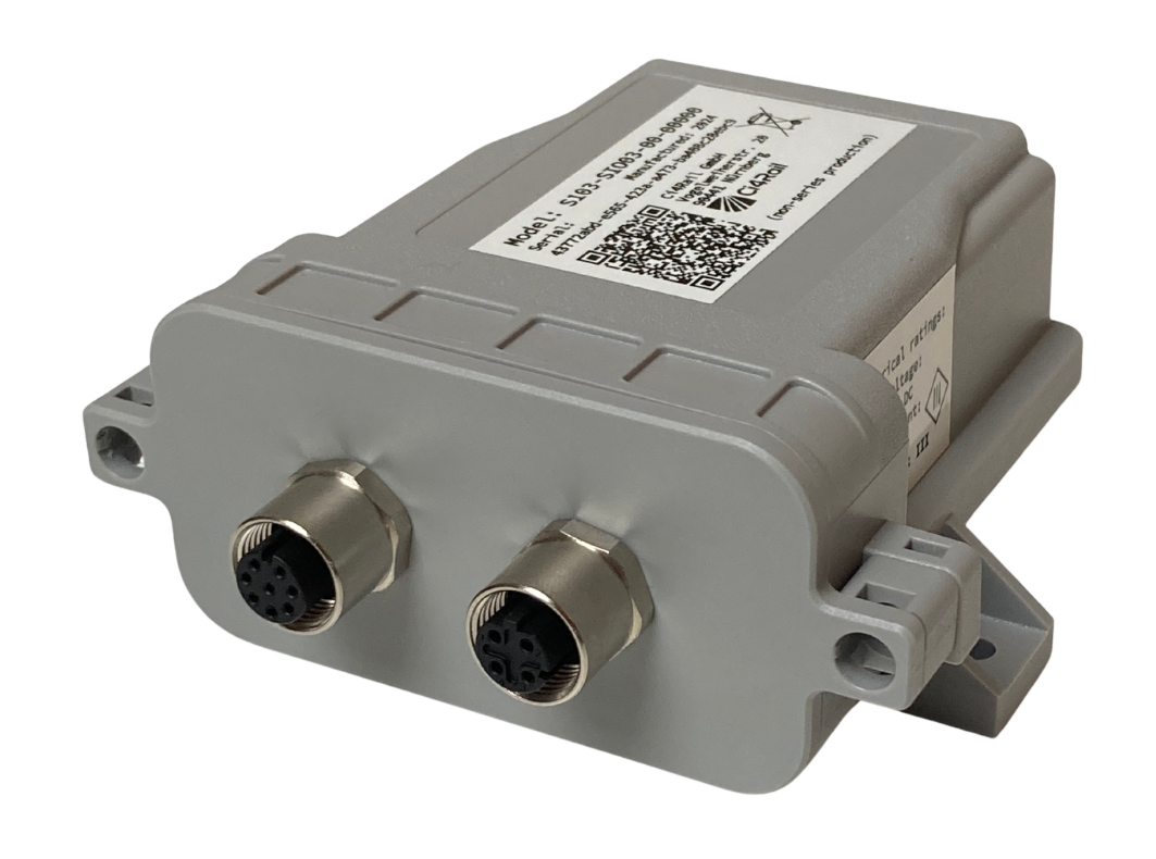
Connections
SIO03 provides two M12 interface connectors for roboust and IP protected connections. The product offers an M12-8pin A-coded connector for shared power and service interfaces as well as an M12-4pin D-coded Ethernet interface connector.
M12-8pin A-coded, socket:
- alt. power supply 12V / 24V DC (nom)
- Ignition
- Wheeltick Input
- USB-Service Interface
Mating connector: M12 8-pin A-coded, plug.
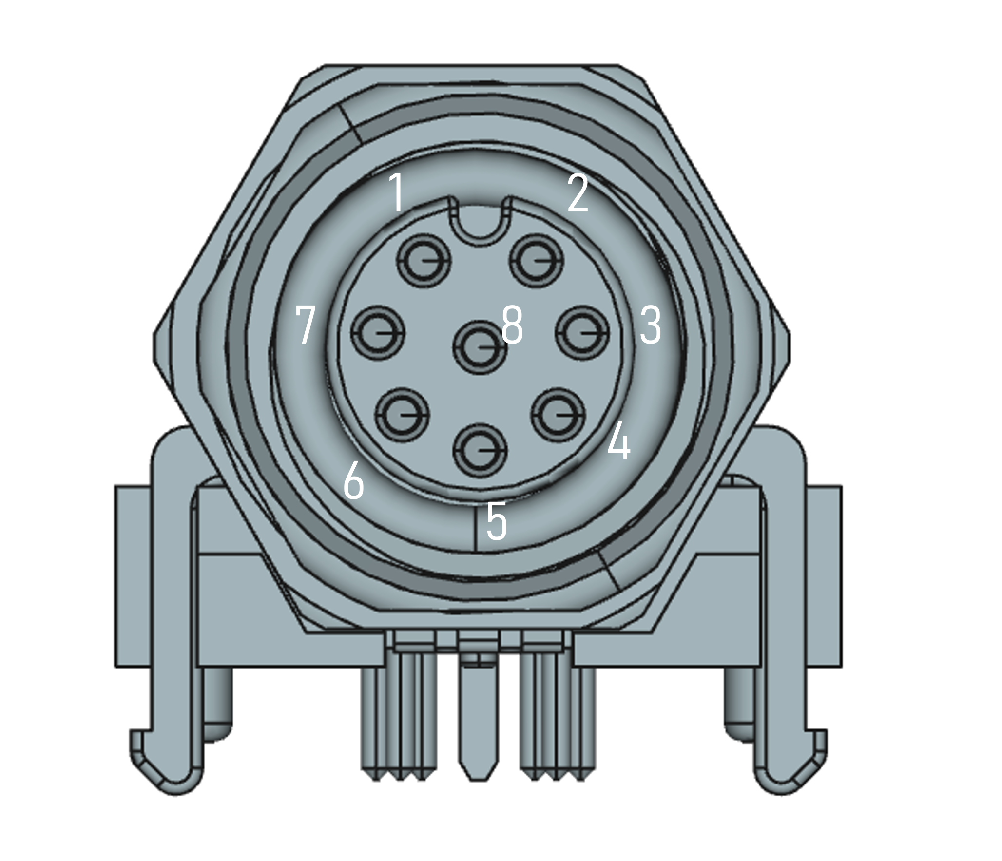
| Pin | Symbol | Description |
|---|---|---|
| 1 | V_IN | 12/24V Power Supply Input |
| 2 | WT | Wheeltic input |
| 3 | IGN | Ignition |
| 4 | USB- | USB Dataline - |
| 5 | GND | Ground |
| 6 | GND | Ground |
| 7 | V_USB | USB Power Supply Input |
| 8 | USB+ | USB Dataline + |
M12-4pin D-coded, socket:
- 100 MBit/s Ethernet; Power Over Ethernet
Mating connector: M12 4-pin DA-coded, plug.
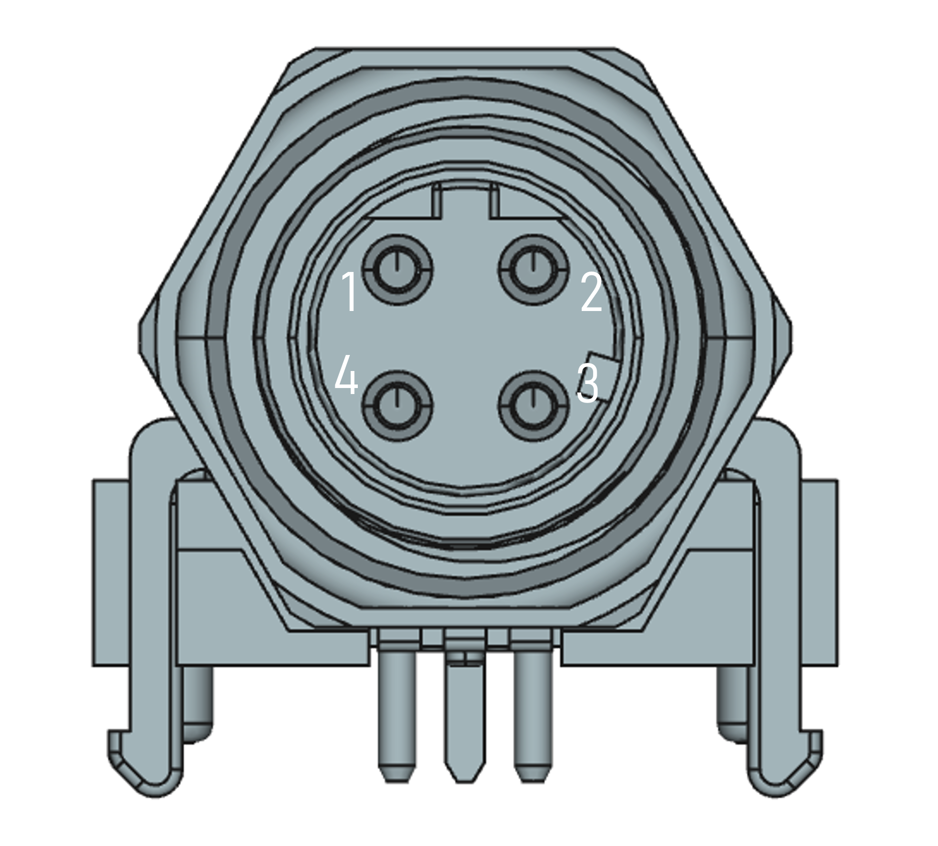
| Pin | Symbol | Description |
|---|---|---|
| 1 | TxD+ | CT (PoE) |
| 2 | RxD+ | CT (PoE) |
| 3 | TxD- | CR (PoE) |
| 4 | RxD- | CR (PoE) |
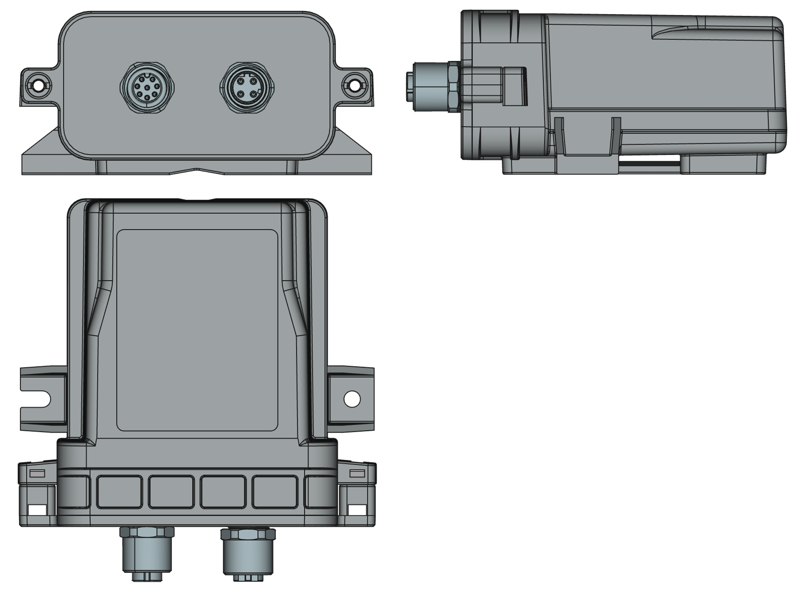
Mechanical Outline
The Tracelet has the following dimensions
| Dimension | Value |
|---|---|
| Length | 110 mm |
| Depth | 98 mm |
| Height | 48 mm |
Mounting & Installation
The tracelets have to be mounted with clear view to GNSS satellites as well as UWB satlet infrastructure. We recommend mounting on roof of vehicle.
Mounting depends on the given conditions per vehicle. Depending on the mounting conditions, specific mounting brackets might be available. Contact Ci4Rail for specific designs of mounting brackets
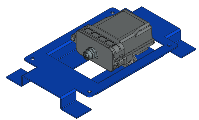
(Picture shows SIO02 but is also valid for SIO03 - mounting is identical)
In some cases, a snow cover might be useful.
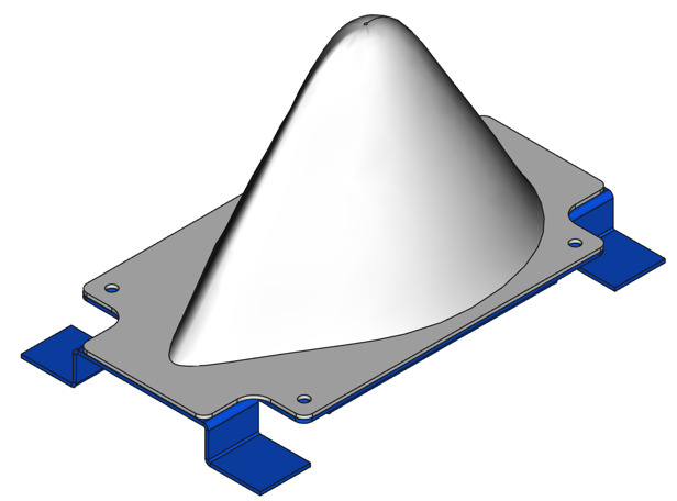
The tracelets have to be mounted in specific orientation to give the best results in positioning. Mounting is done by M5 mounting bolts, lock washers and nuts as shown in the following picture:
(Pictures shows SIO02 but is also valid for SIO03 - mounting is identical)
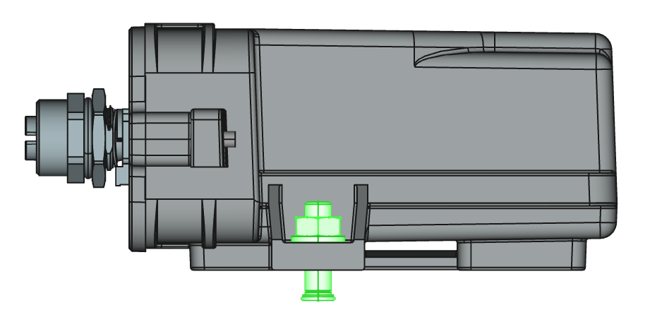
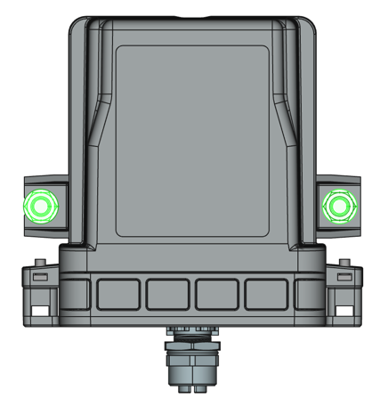
Installation Requirements
Due to integrated inertial measurement unit (IMU), the mounting orientation is essential. The Tracelet has to be mounted with an angle of 0° to ground The Tracelet has to be oriented with the M12 connector towards vehicle back (Cab B).
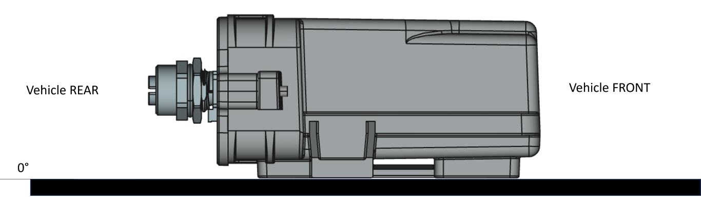
(Picture shows SIO02 but is also valid for SIO03 - mounting is identical)