Configure Tracelet
This section shows how to configure the Tracelet parameters.
UWB Site Origin
The Tracelet can translate UWB site coordinates into WGS84 coordinates. For that the Site latitude, longitude and azimuth must be configured.
Enter these values in fuse-origin parameter.
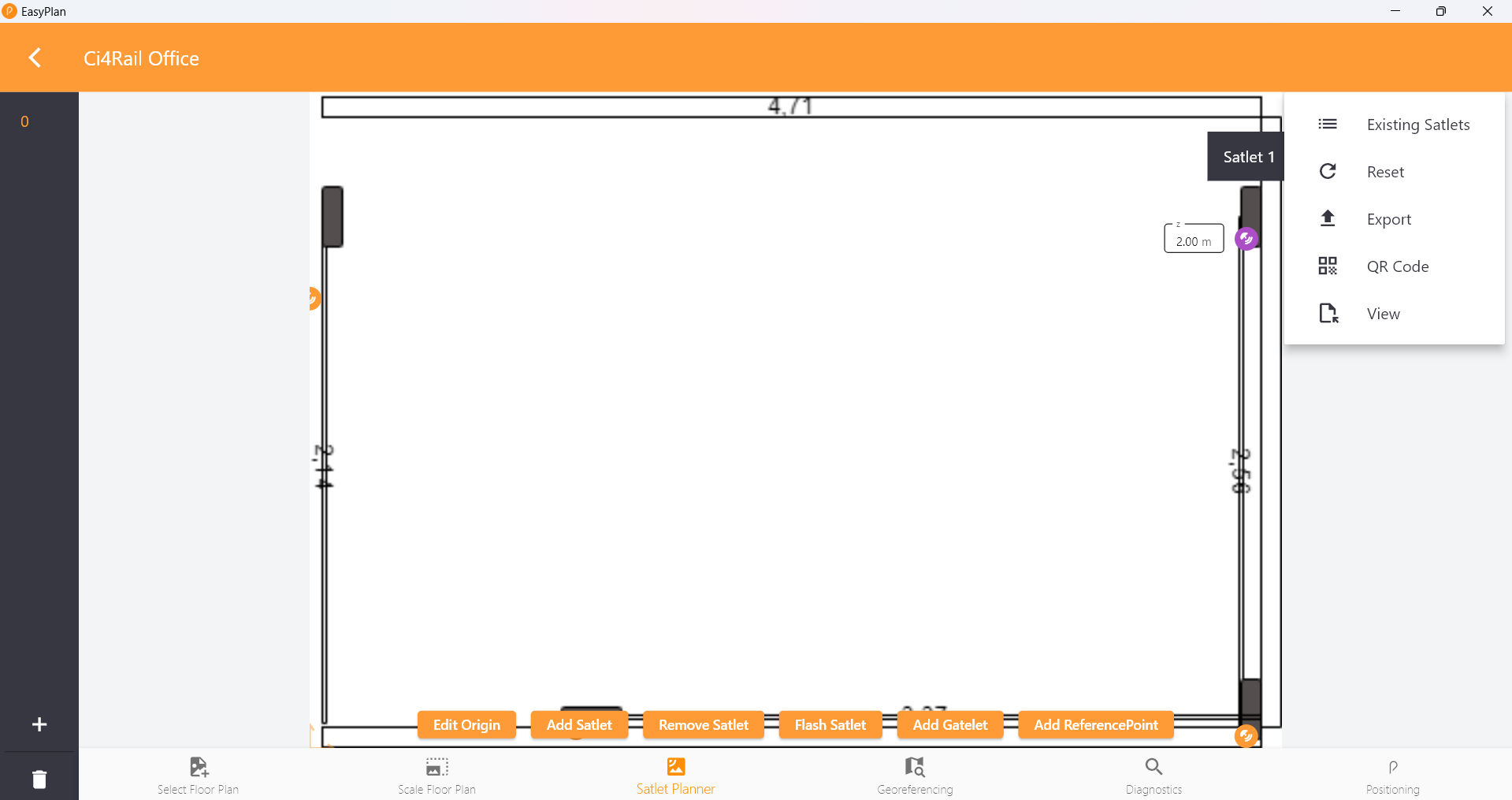
You can get the parameters from Easyplan: Use the “View” feature of the site. A JSON file will be stored in your download folder. In the JSON, look for
    "originAzimuth": xxx,
    "originLatitude": yyy,
    "originLongitude": zzz,
GNSS RTK Correction Data Source
RTK corection data is required to achieve high accuracy. Correction data may come:
- from NTRIP service providers, delivering RTCM correction data, such as Sapos or rtk2go.
- from UBLOX pointperfect, delivering SPARTN correction data.
- from a local RTK Base station + self hosted NTRIP server.
In any case, the device needs to be able to reach the server and the address and credentials must be configured using ntrip-caster and ntrip-credentials parameter.
NOTE: When using pointperfect, you may experience a mismatch of your position on the map. See this article for an explanation.
Using GNSS Sensor Fusion
In GNSS Sensor Fusion mode, the device uses a dynamic model of the vehicle, integrated IMU, and optionally the external wheeltick to further improve the precision, especially in cases with bad GNSS receiption conditions.
To enable GNSS Sensor Fusion mode generally:
- Configure the type of vehicle in parameter
dynmodeltoautomotivefor automotive vehicles, like cars or trucks, andrailfor railway vehicles, like trams. - Configure the alignment of the IMU to the vehicle
- Configure the lever arms
- Configure the wheeltick
- set the
drconfiguration parameter toon.
Lever Arm
The dynamic model for sensor fusion requires the configuration of the lever arm:
- the lever arm from the IMU to the vehicle rotation point (VRP). Because the IMU is inside the tracelet, it can also be read as traclet-to-VRP.
The VRP is defined as the point where the vehicle rotates around.
- For a car, it is the rear axle.
- For a train, this is the center between two bogies.
The configuration parameters are:
imu2vrp_x,imu2vrp_y,imu2vrp_zfor the IMU to VRP lever arm
All parameters are specified in centimeters.
Mount Alignment
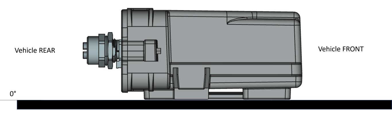
For sensor fusion, the alignment of the IMU to the vehicle is important.
If you mount the tracelet as shown below, you can leave the alignment parameters at their default values (0:0:0).
If the tracelet is not aligned 1:1 there are two possibilities:
- auto-alignment: the device will try to determine the alignment automatically. This is the default. Set the
ubx_mntalgparameter to an empty string to enable auto-alignment. - manual alignment: the alignment can be configured using the
ubx_mntalgparameter. The value is a 3-tuple, specifying yaw (0..360), pitch (-90..90), and roll (-180..180) in degrees, e.g.0:0:0for no alignment.
For more information, refer to the UBlox Integration Manual.
Wheel Tick
If the vehicles wheeltick signal is connected to the device, the wheeltick signal can be used to improve the precision of the positioning.
The number of ticks per km must be configured using the tacho_k parameter.
NOTE: The current tracelet firmware has a fixed wheeltick rate. To change the wheeltick rate, a different firmware must be flashed. The default wheeltick rate is 4000 Ticks/km. If you need a different rate, please contact us. In addition, the tacho_k parameter must fit the firmware.
To enable wheel tick usage, set ubx_wt_dir to 1:0:0:0. To disable wheeltick usage (if you don’t have a wheeltick), set it to 0:0:0:0.
Localization Server Address
Tell the Tracelet where to send the position messages to. Enter the address and port of your localization server. To find out your PC’s address, open a command prompt and enter ipconfig. Look for the IPv4 address of your active WLAN network connection (e.g., 192.168.55.100).
The port of the Localization server is 11001.
Set the parameter loc-srv to <your_pc_ip>:11001.
Device Configuration
The device parameters mentioned above can be configured either via USB console or via network.
All parameters are stored in the device’s non-volatile memory and are persistent across reboots.
After changing a parameter, the device must be rebooted to apply the new configuration. This can be done by entering reboot in the USB console or by sending a restart command via the network.
Setting Parameters via Network
To set parameters via network, use the io4edge-cli tool, This page describes how to download and use this tool.
To apply a set of parameters, use the provided sio02-params-demo.yaml file (part of the lyve-demokit repo) as a starting point and change all parameters according to your needs.
Afterwards, apply them with
c:\work\io4edge-cli\io4edge-cli -i 192.168.55.2:9999 set-parameter -f sio02-params-demo.yaml
c:\work\io4edge-cli\io4edge-cli -i 192.168.55.2:9999 restart
Setting Parameters via USB Console
Only necessary in case you can’t reach the device via network! In this case connect a USB-A cable to the breakout adapter EVU04, start a terminal program on your PC, such as MobaXterm, and connect it with the serial port at baudrate 115200.
You should see some log messages of the device.
Press ENTER and the device will present a config> prompt. Enter the commands to configure the device.
For example, to enable sensor fusion, you would enter:
config> dr on
Enter help to see a list of all available commands. Note that some commands are for development and testing purposes only.
More info: General Device Configuration of io4edge devices
Parameter List
The following table lists the user relevant parameters of the device:
| Parameter | Description | Default | Example |
|---|---|---|---|
| wifi-ssid | SSID of the Wi-Fi network to connect to | ”” | MyWiFi |
| wifi-pw | Password of the Wi-Fi network to connect to | ”” | MyWiFiPassword |
| device-id | Use to identify the device in the network and used for traceled_id in the position message |
”” | TRACELET-DEMO |
| loc-srv | Address of the localization server to send position messages to | ”” | 192.168.0.88:11001 |
| ntp-srv | Address of the NTP server to get time from | pool.ntp.org | pool.ntp.org |
| ntrip-caster | Address of the NTRIP caster to get correction data from (host:port:mountpoint) | ”” | rtk2go.com:2101:LAU01DE |
| ntrip-credentials | Credentials for the NTRIP caster (username:password) | ”” | info@ci4rail.com:none |
| gnss-rate | Rate of GNSS position messages in Hz, 1..4Hz | 1 | 3 |
| fuse-rate | Rate of fused position messages in Hz, 1..4Hz. Set it to the same value as `gnss-rate | 1 | 3 |
| fuse-origin | UWB Site origin and azimuth (lat:lon:azi) | ”” | 48.1748314:11.5287476:0.8900383 |
| dr | Enable GNSS sensor fusion | on | on |
| dynmodel | Dynamic model of the vehicle (rail, automotive) | automotive | rail |
| imu_mntalg | Manual alignment of the device to the vehicle (yaw:pitch:roll). If parameter is not set, use auto mount alignment | ”” | -90:0:0 |
| imu2vrp_x, imu2vrp_y, imu2vrp_Z | Lever arm from IMU to VRP in cm | 0 | 100 |
| uwb_z | Tracelet mounting height (to floor) in cm | 0 | 280 |
| tacho_k | Number of ticks per km for the wheeltick signal | 0 | 4000 |
| ubx_wt_dir | Enable wheeltick usage (1:0:0:0) or disable wheeltick usage (0:0:0:0) | 0:0:0:0 | 1:0:0:0 |
| uwb_radio | UWB channel to use (5 or 9) - Must be 9 for LYVE Demokit Rev. 0 | 5 | 9 |