SIO04-99 Detailed Description
Introduction
The GNSS RTK precise positioning module SIO04-99 is a member of the KYT Sensor family by Ci4Rail and can work as a standalone device as well as in combination with ModuCop MEC0x.
The GNSS/RTK technology provides high precision positioning information. The speed pulse input signal and the integrated IMU together with specific movement models allow for precise positioning even in areas with poor GNSS reception.
The positioning information is transferred to in-vehicle subsystems via Ethernet interface.
NOTE: The SIO04-99 is a temporary prototyping unit. It will be subsituted by the “real” SIO04 when available.
Specification
| Feature | Value |
|---|---|
| Interfaces | |
| Communication Interface | 100MBit/s Ethernet via M12 D-Coded |
| Service Interface | USB 2.0 via M12 8p A-Coded |
| Positioning Outdoor | Multi-band GNSS/RTK |
| GPS/QZSS (L1C/A L2C) | |
| GLONASS (L1OF L2OF) | |
| Galileo (E1B/C E5b) | |
| BeiDou (B1I B2I) | |
| Position accuracy | localization values have an accuracy of < 1m for 95% of the reported values |
| Speed Pulse Signal | acc. to IEC 16844-2 (input high: 4,8V; input low: 2,2V) |
| Ignition | On State: Input high: 5,2 V (min) or open |
| Standby State (after delay ~3 sec): Input low: 3,6 V (max) | |
| Antenna | External GNSS Antenna supporting L1 and L2 band, 3V supply voltage, max 60mA |
| Maintenance | |
| Firmware update | Via USB, LAN |
| Management | Via io4edge protocol, see io4edge protocol |
| Electrical | |
| Power Supply | Power-over-Ethernet (PoE PD) class 1 |
| 12V, 24V (nom.) acc. to ISO 7637-2:2011 via M12 8p A-Coded | |
| Power Consumption | Operation typ. < 3 W |
| Standby State < 0,1 W | |
| Mechanics | |
| Dimensions (w/o mounting acc) | Width: 71.0 mm |
| Depth: 61.2 mm | |
| Height: 111.5 mm | |
| Mounting | Flexible Mounting: Wall mount, mounting as 19” cassette, or DIN Rail |
| Ingress Protection | IP40 |
| Environmental | |
| Operating | -40…+70°C (EN 50155:2021 - OT4) |
| Storage Temperature | -40…+85°C |
| Humidity | 95% (EN 50155-1:2021) |
| Altitude | 3000 m max. above sea level (EN 50125-1:2014, class AX) |
| Shock / Vibration | EN 61373:2010; Cat. 1; Class B |
| EMC Emission / Immunity | EN 50121-3-2:2016; EMV 06 Class S1 / ECE R10 Rev.6 |
| Safety | EN 50155:2017; EN 50153:2014+A1:2017; EN 50124-1:2017; EN 62368-1:2016; EN ISO 13732-1:2008 |
| Fire & Smoke | EN 45545-2:2013 + A1:2015; HL3 |
| Useful Life | 20 years (EN 50155:2017, class L4) |
| Certifications | TBD |
Connections
SIO04-99 provides two M12 interface connectors for roboust and IP protected connections. The product offers an M12-8pin A-coded connector for shared power and service interfaces as well as an M12-4pin D-coded Ethernet interface connector.
M12-8pin A-coded, socket
- alt. power supply 12V / 24V DC (nom)
- Ignition
- Wheeltick Input
- USB-Service Interface
Mating connector: M12 8-pin A-coded, plug.
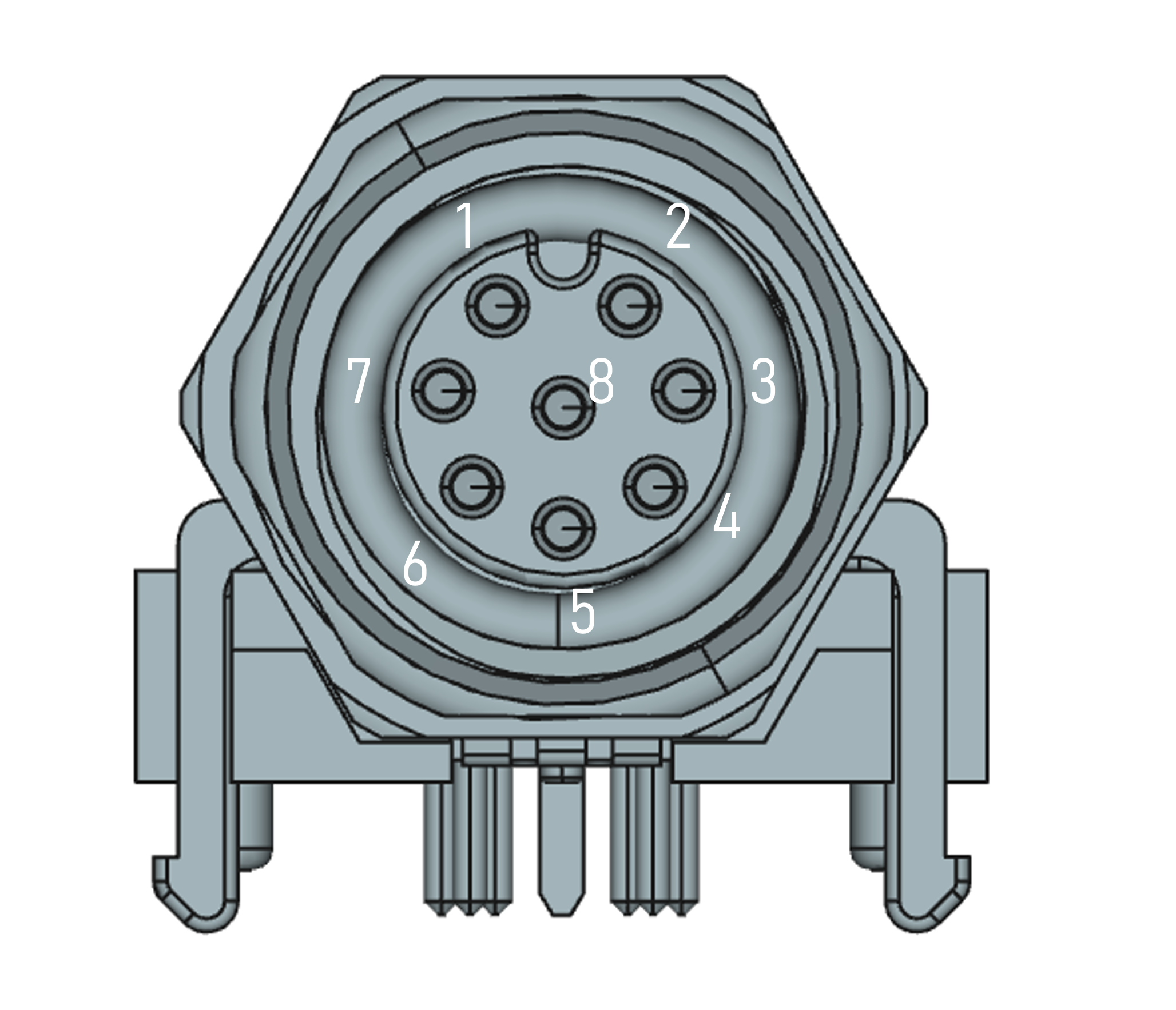
| Pin | Symbol | Description |
|---|---|---|
| 1 | V_IN | 12/24V Power Supply Input |
| 2 | WT | Wheeltic input |
| 3 | IGN | Ignition |
| 4 | USB- | USB Dataline - |
| 5 | GND | Ground |
| 6 | GND | Ground |
| 7 | V_USB | USB Power Supply Input |
| 8 | USB+ | USB Dataline + |
M12-4pin D-coded, socket
- 100 MBit/s Ethernet; Power Over Ethernet
Mating connector: M12 4-pin D-coded, plug.
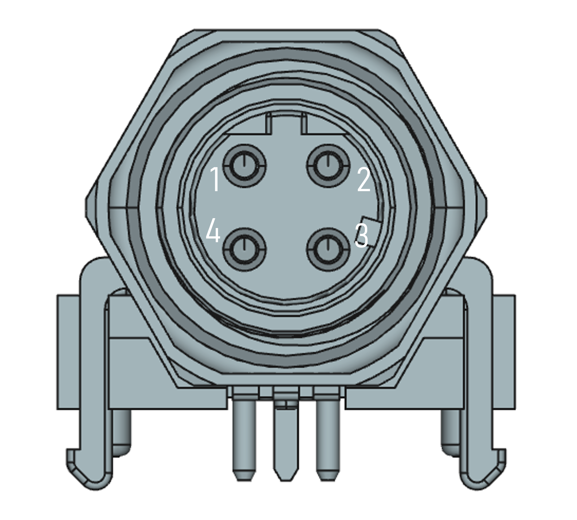
| Pin | Symbol | Description |
|---|---|---|
| 1 | TxD+ | CT (PoE) |
| 2 | RxD+ | CT (PoE) |
| 3 | TxD- | CR (PoE) |
| 4 | RxD- | CR (PoE) |
Functional Description
After power on, the device uses its configuration parameters to configure its GNSS receiver. It will then periodically send its acquired position in a “position message” to the “localization server” (which may be your application). This message contains the WGS84 coordinates and many other parameters known to the device, such as quality metrics. The position message is sent always, even if no GNSS fix has been achieved.
To achieve high precision, the GNSS RTK receiver must be fed with correction data using a network connection to the correction data server.
Optionally, the device can be configured to apply “GNSS sensor fusion”. In this mode, the device uses a dynamic model of the vehicle, integrated IMU, and the external wheeltick to further improve the precision, especially in cases with bad GNSS receiption conditions. GNSS sensor fusion however requires additional configuration of the device.
Optionally, the device may be configured to connect to a NTP (network time protocol) server. It uses the NTP time to timestamp its messages in case no time from GNSS is available.

Position Messages
The device sends position messages to the address configured with the parameter loc-srv, which must be the host address (name or IP address) plus the port, e.g. 192.168.0.88:11002.
The rate of the transmission can be configured from 1 to 4 Hz, using the parameters gnss-rate and fuse-rate, which should be set to the same value, e.g. 3 for 3 positions per second.
Tranmission Protocol
The protocol to transfer position messages is UDP with application level acknowledgement. The device is the client and initiates the communication.
A python example for a server receiving the position messages is here.
Client datagram:
- UDP header
- sequence number (4 byte, little endian)
- payload (serialized protobuf data)
Server datagram (ACK)
- UDP header
- sequence number (4 byte, little endian)

Message Content
The message payload is encoded using Protobuf. The message is described here. In this repository, there are also pre-compiled protobuf definitions for several programming languages.
Notes:
- the
traceled_idis reflecting thedevice_idconfiguration parameter. - the device is not supporting UWB for indoor positioning, so the UWB related fields are missing in the message. The
fusedsub-message should be ignored, as it would only make sense in combination with UWB. - the
directionfield is currently unsupported speedandmileageare calculated from the wheeltick input. They remain 0 if no wheeltick is connected.- The
metricssub-message contains many quality metrics. This sub-message is generated only every 3 seconds, so the metrics are not present in every message.
RTK Correction Data
RTK corection data is required to achieve high accuracy. Correction data may come from:
- from NTRIP service providers, delivering RTCM correction data, such as Sapos or rtk2go.
- from UBLOX pointperfect, delivering SPARTN correction data.
- from a local RTK Base station + self hosted NTRIP server.
In any case, the device needs to be able to reach the server and the address and credentials must be configured using ntrip-caster and ntrip-credentials parameter.
In the position message, the metric ntrip_is_connected will reflect whether connect to the server has succeeded.
The GNSS fix type will change to 4 (RTK Fix) or 5(RTK Float) when correction data is available. 5 means that correction data is available but can’t be applied.
Using GNSS Sensor Fusion
In GNSS Sensor Fusion mode, the device uses a dynamic model of the vehicle, integrated IMU, and optionally the external wheeltick to further improve the precision, especially in cases with bad GNSS receiption conditions.
To enable GNSS Sensor Fusion mode generally:
- Configure the type of vehicle in parameter
dynmodeltorailfor railway vehicles, like trains or trams - Configure the alignment of the IMU to the vehicle
- Configure the lever arms
- Configure the wheeltick
- set the
drconfiguration parameter toon.
Lever Arms
The dynamic model for sensor fusion requires the configuration of two lever arms:
- the lever arm from the GNSS antenna to the IMU (the IMU inside the device)
- the lever arm from the IMU to the vehicle rotation point (VRP)
The VRP is defined as the point where the vehicle rotates around. For a train, this is the center between two bogies.
The configuration parameters are:
imu2vrp_x,imu2vrp_y,imu2vrp_zfor the IMU to VRP lever armimu2ant_x,imu2ant_y,imu2ant_zfor the IMU to GNSS antenna lever arm
All parameters are specified in centimeters.
Here is a typical example for a train. The values are not to scale:

IMU Mount Alignment
If sensor fusion is enabled, the alignment of the IMU to the vehicle is important.
The axes of the device are defined as follows:

If the IMU is not aligned 1:1 there are two possibilities:
- auto-alignment: the device will try to determine the alignment automatically. This is the default. Set the
imu_mntalgparameter to an empty string to enable auto-alignment. - manual alignment: the alignment can be configured using the
imu_mntalgparameter. The value is a 3-tuple, specifying yaw (0..360), pitch (-90..90), and roll (-180..180) in degrees, e.g.0:0:0for no alignment.
For more information, refer to the UBlox Integration Manual.
Wheel Tick
If the vehicles wheeltick signal is connected to the device, the wheeltick signal can be used to improve the precision of the positioning. The wheeltick signal is a signal that is generated by the vehicle and reflects the distance traveled by the vehicle. The wheeltick signal is used to correct the GNSS positioning, especially in cases where the GNSS signal is weak or not available.
The wheeltick signal is connected to the device on the WT and GND pins of the M12-8pin A-coded connector. The signal should have a voltage of >=4.8V (max 36V) when high and <=2.2V when low.
The number of ticks per km must be configured using the tacho_k parameter.
To enable wheel tick usage, set ubx_wt_dir to 1:0:0:0. To disable wheeltick usage (if you don’t have a wheeltick), set it to 0:0:0:0.
Checking the Sensor Fusion Status
When sensor fusion is enabled for the first time, it takes a while until the device has collected enough data to use the IMU and wheeltick for sensor fusion.
The position message metrics.ubx_sensor_fusion_status_enum reflects the status of the sensor fusion calibration:
0means that the sensor fusion is not yet calibrated1means that the sensor fusion is calibrated and is using the IMU and wheeltick for positioning.2means “suspended”, i.e. the sensor fusion is not used for positioning because the device has detected inconsistencies in the data.3means “disabled”, i.e. the sensor fusion is disabled (when thedrparameter is set tooff).
Ignition Signal
The ignition signal (IGN) is used only when the device is supplied via Power Input (V_IN). When the device is powered via PoE or USB, the ignition signal is not used.
IGN must be active (high) to power on the device. The device will power off after a delay of 5 seconds when the IGN signal goes low.
Device Configuration
The device parameters mentioned above can be configured either via USB console or via network.
All parameters are stored in the device’s non-volatile memory and are persistent across reboots.
After changing a parameter, the device must be rebooted to apply the new configuration. This can be done by entering reboot in the USB console or by sending a restart command via the network.
Setting Parameters via USB Console
The device can be configured via the USB console. Connect the device to a computer using a USB cable and start a terminal program. You should see some log messages of the device.
Press ENTER and the device will present a config> prompt. Enter the commands to configure the device.
For example, to enable sensor fusion, you would enter:
config> dr on
Enter help to see a list of all available commands. Note that some commands are for development and testing purposes only.
More info: General Device Configuration of io4edge devices
Setting Parameters via Network
To set parameters via network, use the io4edge-cli tool, This page describes how to download and use this tool.
Parameters
The following table lists the user relevant parameters of the device:
| Parameter | Description | Default | Example |
|---|---|---|---|
| device-id | Use to identify the device in the network and used for traceled_id in the position message |
”” | SIO04-99-1 |
| loc-srv | Address of the localization server to send position messages to | ”” | 192.168.0.88:11002 |
| ntp-srv | Address of the NTP server to get time from | pool.ntp.org | pool.ntp.org |
| ntrip-caster | Address of the NTRIP caster to get correction data from (host:port:mountpoint) | ”” | rtk2go.com:2101:LAU01DE |
| ntrip-credentials | Credentials for the NTRIP caster (username:password) | ”” | info@ci4rail.com:none |
| gnss-rate | Rate of GNSS position messages in Hz, 1..4Hz | 1 | 3 |
| fuse-rate | Rate of fused position messages in Hz, 1..4Hz. Set it to the same value as `gnss-rate | 1 | 3 |
| fuse-origin | Note relevant for this device, but MUST BE SET TO A NON-EMPTY VALUE. Otherwise, no position messages are generated | ”” | 0:0:0 |
| dr | Enable GNSS sensor fusion | on | on |
| dynmodel | Dynamic model of the vehicle (rail, automotive) | automotive | rail |
| imu_mntalg | Manual alignment of the IMU to the vehicle (yaw:pitch:roll). If parameter is not set, use auto mount alignment | ”” | -90:0:0 |
| imu2vrp_x, imu2vrp_y, imu2vrp_Z | Lever arm from IMU to VRP in cm | 0 | 100 |
| imu2ant_x, imu2ant_y, imu2ant_z | Lever arm from IMU to GNSS antenna in cm | 0 | 100 |
| tacho_k | Number of ticks per km for the wheeltick signal | 0 | 1000 |
| ubx_wt_dir | Enable wheeltick usage (1:0:0:0) or disable wheeltick usage (0:0:0:0) | 0:0:0:0 | 1:0:0:0 |