IOU06 Detailed Description
CAN/COM Interface
The IOU06 has a shared CAN/COM interface on the topmost D-Sub Connector. The interface can be used as a CAN interface or as a serial interface, but not both at the same time.
Connection
CAN/COM port connector on IOU06 (Rev. 0):
CAN/COM port connector on IOU06 (Rev. 1):

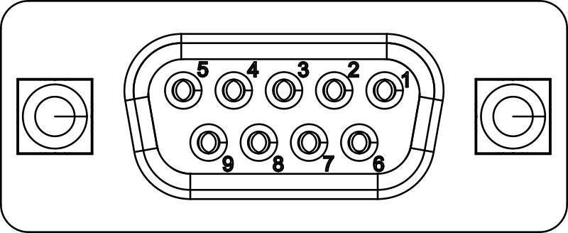
Pin functionality as viewed from IOU06:
| Pin | Symbol | Description |
|---|---|---|
| 1 | COM_TX+ | RS485 positive transmit line |
| 2 | CAN_L | CAN Signal (dominant low) |
| 3 | GND_ISO | CAN/RS485 Ground |
| 4 | COM_RX+ | RS485 positive receive line |
| 5 | - | not connected |
| 6 | COM_TX- | RS485 negative transmit line |
| 7 | CAN_H | CAN Signal (dominant high) |
| 8 | - | not connected |
| 9 | COM_RX- | RS485 negative receive line |
COM Interface
Features
- RS485-full-duplex or RS485-half-duplex
- Virtual tty support using RFC2217
- Appears as a standard tty device on Linux hosts
- Baudrates up to 460800 Baud
- Galvanic Isolation between the COM port and other ports
Typical Connection Examples (Rev. 0)

Typical Connection Examples (Rev. 1)

Important Notes:
For RS485/RS422 half-duplex operation, you must externally connect the COM ports Rx pins with the corresponding Tx pin
In RS485/RS422 mode, please add termination resistors to the end of the line. The termination must be 120R at each end of the cable.
Operating Principle of IP Based COM-Port
The COM port on the IOU06 is exposed to the network as a ttynvt (network virtual terminal) service. For the COM port, a TCP-Server, implementing the RFC2217 protocol is active on the IOU06.
RFC2217 extends the telnet protocol by adding COM port configuration commands, flow control and more. In addition to RFC2217 standard, we have added a proprietary extension for IOU06 to control half duplex operation. (See TNS_CTL_ENABLE_RS485 and TNS_CTL_DISABLE_RS485 in the telnet header file)
To access the COM port from the host, you can
- Use the ttynvt program to create a virtual
/dev/ttydevice for each COM port. - Use pyserial’s RFC2217 support
Using ttynvt
An instance of ttynvt must be started for each virtual RFC2217 COM port. ttynvt creates a device entry in /dev, e.g. /dev/ttyS101-IOU06-USB-EXT-1-com. Your application can then use this device as any other tty device in the system.
If you are using a Linux Image from Ci4Rail, ttynvt instances are automatically started for each ttynvt COM port in the network via ttynvt-runner. ttynvt-runner is started as a systemd service.
Using Half Duplex Mode with ttynvt
Half duplex mode must be used with the RS485/RS422 signals on the connector. In half duplex mode, two or more participants share the Rx/Tx lines. Only one participant is allowed to drive the Tx data.
To enable half duplex mode, the application must call iotcl TIOCSRS485 on the tty device provided by ttynvt. In python, this can be done like this:
import serial
import serial.rs485

ser = serial.Serial(
                port="/dev/S101-IOU06-USB-EXT-1-com",
                baudrate = 115200,
                parity=serial.PARITY_NONE,
                stopbits=serial.STOPBITS_ONE,
                bytesize=serial.EIGHTBITS,
                timeout=1,
                rtscts = False
            )

# Set half duplex operation
ser.rs485_mode = serial.rs485.RS485Settings()

ser.write(bytes("Hello World", "utf8"))

data = ser.read(10)
print("data: {}".format(data))
NOTE: In half duplex mode, the data that is sent to the line is NOT echoed back to the application, because the receiver is disabled while sending.
Using pyserial with RFC2217
pyserial provides a way to communicate directly with RFC2217 compliant servers, this way, ttynvt is not required.
The following example opens COM1 of the IOU06 with device id S101-IOU06-USB-EXT-1 (port 10000 is the port for COM1), sets the baudrate to 19200 and sends and receives some characters:
import serial

ser = serial.serial_for_url("rfc2217://S101-IOU06-USB-EXT-1.local:10001?ign_set_control")
ser.baudrate = 19200

ser.write(bytes("Hello World", "utf8"))

data = ser.read(10)
print("data: {}".format(data))
NOTE pyserial with RFC2217 does not support the proprietary extension to set the COM port into half duplex mode. Therefore, half-duplex mode is not supported.
Considerations when running with Handshaking enabled
The COM port supports software (XON/XOFF) handshaking for flow control. A receiver may stop the sender by sending an XOFF character.
However, be aware about the following behaviour: When the IOU06 is the sender and the connected receiver forces the transmission to stop, the IOU06 may hang until the transmission is re-enabled again by the receiver. Even if you stop the transmitting process, the firmware will not accept any new connection request until its transmit buffer gets empty.
If you run into such a situation and the receiver will never re-enable the transmission , you must restart the IOU06, for example using the io4edge-cli.
CANBus Interface
Typical Connection Examples (Rev. 0)

Typical Connection Examples (Rev. 1)

Features
- ISO 11898 CANBus Interface, up to 1MBit/s
- Usable for direct I/O or as data logger with multiple data streams.
- SocketCAN Support
- Standard and Extended Frame Support
- RTR Frame Support
- Fixed Listen Only Mode
- One Acceptance Mask/Filter
Connection
Using the io4edge API to access CAN Function
First, install the io4edge client library.
Want to have a quick look to the examples? See our Github repository.
First, install the io4edge client library.
Want to have a quick look to the examples? See our Github repository.
Connect to the CAN Function
To access the CAN Function, create a Client and save it to the variable c. Pass as address either a service address or an ip address with port. Example:
- As a service address:
S101-IOU06-USB-EXT-1-can - As an IP/Port: e.g.
192.168.201.1:10002
We need this client variable for all further access methods.
import (
  "fmt"
  "os"
  "time"
  "github.com/ci4rail/io4edge-client-go/canl2"
  fspb "github.com/ci4rail/io4edge_api/canL2/go/canL2/v1alpha1"
)

func main() {
  const timeout = 0 // use default timeout

  c, err := canl2.NewClientFromUniversalAddress("S101-IOU06-USB-EXT-1-can", timeout)
  if err != nil {
    log.Fatalf("Failed to create canl2 client: %v\n", err)
  }
}
To access the CAN Function, create a Client and save it to the variable can_client. Pass as address either a service address or an ip address with port. Examples:
- As a service address:
S101-IOU06-USB-EXT-1-can - As an IP/Port:
192.168.201.1:10000
We need this client variable for all further access methods.
import io4edge_client.canl2 as canl2
import io4edge_client.functionblock as fb

def main():
  can_client = canl2.Client("S101-IOU06-USB-EXT-1-can")
Bus Configuration
There are two ways to configure the CAN function:
- Using a persistent parameter that is stored in the flash of the IOU06, as described here.
- Temporarily, via the io4edge CANL2 API, as shown below
Temporary Bus Configuration
When applying a configuration via the API, the configuration is only active until the next restart of the device. The configuration is not stored in flash. When the device is restarted, it will apply the persistent configuration stored in flash, or - if no persistent configuration is available - will keep the CAN controller disabled.
Bus Configuration can be set via UploadConfiguration.
  err = c.UploadConfiguration(
    canl2.WithBitRate(125000),
    canl2.WithSamplePoint(0.625),
    canl2.WithSJW(1),
    canl2.WithListenOnly(false),
  )
Bus Configuration can be set via upload_configuration.
Note: The sample point is given as a thousandth of a percent, e.g. 625 for 62.5%.
    can_client.upload_configuration(
        canl2.Pb.ConfigurationSet(
            baud=125000,
            samplePoint=625,
            sjw=1,
            listenOnly=False,
        )
    )
Receiving CAN Data
To receive data from the CANbus, the API provides functions to start a Stream.
In the stream the firmware generates Buckets, where each Bucket contains a number of Samples. Each sample contains:
- A timestamp of the sample
- The CAN frame (may be missing in case of bus state changes or error events)
- The CAN Bus state (Ok, error passive or bus off)
- Error events (currently: receive buffer overruns)
For efficiency, multiple samples are gathered are sent as one Bucket to the host.
Without any parameters, the stream receives all CAN frames:
// start stream
err = c.StartStream()
Missing parameters to ´StartStream` will take default values:
- Filter off (let all CAN frames pass through)
- Maximum samples per bucket: 25
- Buffered Samples: 50
- Keep Alive Interval: 1000ms
- Low Latency Mode: off
  for {
    // read next bucket from stream
    sd, err := c.ReadStream(time.Second * 5)

    if err != nil {
      log.Printf("ReadStreamData failed: %v\n", err)
    } else {
      samples := sd.FSData.Samples
      fmt.Printf("got stream data with %d samples\n", len(samples))

      for _, s := range samples {
        fmt.Printf("  %s\n", dumpSample(s))
      }
    }
  }

func dumpSample(sample *fspb.Sample) string {
  var s string

  s = fmt.Sprintf("@%010d us: ", sample.Timestamp)
  if sample.IsDataFrame {
    f := sample.Frame
    s += "ID:"
    if f.ExtendedFrameFormat {
      s += fmt.Sprintf("%08x", f.MessageId)
    } else {
      s += fmt.Sprintf("%03x", f.MessageId)
    }
    if f.RemoteFrame {
      s += " R"
    }
    s += " DATA:"
    for _, b := range f.Data {
      s += fmt.Sprintf("%02x ", b)
    }
    s += " "
  }
  s += "ERROR:" + sample.Error.String()
  s += " STATE:" + sample.ControllerState.String()

  return s
}
    # start stream, accept all frames
    stream_start = canl2.Pb.StreamControlStart(
        acceptanceCode=0, acceptanceMask=0
    )

    can_client.start_stream(
        stream_start,
        fb.Pb.StreamControlStart(
            bucketSamples=100,
            keepaliveInterval=1000,
            bufferedSamples=200,
            low_latency_mode=False,
        ),
    )

    while True:
        try:
            generic_stream_data, stream_data = can_client.read_stream(timeout=3)
        except TimeoutError:
            print("Timeout while reading stream")
            continue

        print(
            "Received %d samples, seq=%d" % (len(stream_data.samples), generic_stream_data.sequence)
        )

        for sample in stream_data.samples:
            print(sample_to_str(sample))


def sample_to_str(sample):
    ret_val = "%10d us: " % sample.timestamp
    if sample.isDataFrame:
        frame = sample.frame
        ret_val += "ID:"
        if frame.extendedFrameFormat:
            ret_val += "%08X" % frame.messageId
        else:
            ret_val += "%03X" % frame.messageId
        if frame.remoteFrame:
            ret_val += " R"
        ret_val += " DATA:"
        for i in range(len(frame.data)):
            ret_val += "%02X " % frame.data[i]
        ret_val += " "

    ret_val += "ERROR: " + canl2.Pb._ERROREVENT.values_by_number[sample.error].name
    ret_val += (
        " STATE: "
        + canl2.Pb._CONTROLLERSTATE.values_by_number[sample.controllerState].name
    )
    return ret_val
NOTE: At the moment, timestamps are expressed in micro seconds relative to the start of the IOU06. Future client libraries will map the time to the host’s time domain
Controlling the Stream
The stream behavior can be fine-tuned to the application needs. If you do not specify any parameters, the default values are used.
-
The
BucketSamplesparameter (default:25) defines the number of samples per bucket. If the bucket containsBucketSamples, it is sent to the client. -
The
KeepAliveIntervalparameter (default:1000) defines the maximum time in ms between two buckets. If the bucket is not full, it is sent after the configured interval. -
The
BufferedSamplesparameter (default:50) defines the number of samples that can be buffered in the device. If the buffer is full, the oldest samples are overwritten. As a rule of thumb,BufferedSamplesshould be at least two times theBucketSamples. Select a higher number if your reception process is slow to avoid buffer overruns. -
If you want low latency on the received data, you can enable the “low latency” mode by using
LowLatencyMode(default:false). In this mode, samples are sent as soon as possible after they have been received. This means that the buckets contain1..BufferedSamplessamples.
  // configure stream to send the bucket at least once a second
  // configure the maximum samples per bucket to 25
  // configure low latency mode
  // configure the buffered samples to 200
  err = c.StartStream(
      canl2.WithFBStreamOption(functionblock.WithKeepaliveInterval(1000)),
      canl2.WithFBStreamOption(functionblock.WithBucketSamples(25)),
      canl2.WithFBStreamOption(functionblock.WithLowLatencyMode(true))
      canl2.WithFBStreamOption(functionblock.WithBufferedSamples(200)),
  )
If you don’t want to receive all CAN identifiers, you can specify an acceptance code and mask that is applied to each received frame. The filter algorithm is pass_filter = (code & mask) == (received_frame_id & mask).
The same filter is applied to extended frames and standard frames.
  // apply a filter. Frames with an identifier of 0x1xx pass the filter, other frames are filtered out
  code := 0x100
  mask := 0x700
  err = c.StartStream(
    canl2.WithFilter(code, mask),
  )
The stream behavior can be fine-tuned to the application needs:
-
The
bucketSamplesparameter defines the number of samples per bucket. If the bucket containsbucketSamples, it is sent to the client. -
The
keepAliveIntervalparameter defines the maximum time in ms between two buckets. If the bucket is not full, it is sent after the configured interval. -
The
bufferedSamplesparameter defines the number of samples that can be buffered in the device. If the buffer is full, the oldest samples are overwritten. As a rule of thumb,bufferedSamplesshould be at least two times thebucketSamples. Select a higher number if your reception process is slow to avoid buffer overruns. -
If you want low latency on the received data, you can enable the “low latency” mode by setting
low_latency_modetoTrue. In this mode, samples are sent as soon as possible after they have been received. This means that the buckets contain1..bufferedSamplessamples.
If you don’t want to receive all CAN identifiers, you can specify an acceptance code and mask that is applied to each received frame. The filter algorithm is pass_filter = (code & mask) == (received_frame_id & mask).
The same filter is applied to extended frames and standard frames.
    # apply a filter. Frames with an identifier of 0x1xx pass the filter, other frames are filtered out
    stream_start = canl2.Pb.StreamControlStart(
        acceptanceCode=0x100, acceptanceMask=0x700
    )

    can_client.start_stream(
        stream_start,
        fb.Pb.StreamControlStart(
            bucketSamples=100,
            keepaliveInterval=1000,
            bufferedSamples=200,
            low_latency_mode=args.lowlatency,
        ),
    )
Error Indications and Bus State
The samples in the stream contain also error events and the current bus state.
Error events can be:
ErrorEvent_CAN_NO_ERROR- no eventErrorEvent_CAN_RX_QUEUE_FULL- either the CAN controller dropped a frame or the stream buffer was full
Each sample contains also the bus state. When the bus state changes, a sample without a CAN frame may be generated.
Furthermore, client method GetCtrlState may be used to query the current status.
Bus States can be:
ControllerState_CAN_OK- CAN controller is “Error Active”ControllerState_CAN_ERROR_PASSIVE- CAN controller is “Error Passive”ControllerState_CAN_BUS_OFF- CAN controller is bus off
Error events can be:
canl2.Pb.ErrorEvent.CAN_NO_ERROR- no eventcanl2.Pb.ErrorEvent.CAN_RX_QUEUE_FULL- either the CAN controller dropped a frame or the stream buffer was full
Each sample contains also the bus state. When the bus state changes, a sample without a CAN frame may be generated.
Furthermore, client method ctrl_state may be used to query the current status.
Bus States can be:
canl2.Pb.ControllerState.CAN_OK- CAN controller is “Error Active”canl2.Pb.ControllerState.CAN_ERROR_PASSIVE- CAN controller is “Error Passive”canl2.Pb.ControllerState.CAN_BUS_OFF- CAN controller is bus off
Sending CAN Data
To send CAN data, prepare a batch of frames to be sent and call SendFrames.
    // prepare batch of 10 frames
    frames := []*fspb.Frame{}

    for j := 0; j < 10; j++ {
      f := &fspb.Frame{
        MessageId:           uint32(0x100),
        Data:                []byte{},
        ExtendedFrameFormat: false,
        RemoteFrame:         false,
      }
      len := j % 8
      for k := 0; k < len; k++ {
        f.Data = append(f.Data, byte(j))
      }
      frames = append(frames, f)
    }
    // send frames at once
    err = c.SendFrames(frames)

    if err != nil {
      log.Printf("Send failed: %v\n", err)
    }
If you want a high send throughput, it is important not to call SendFrames with only a single frame. If you do so, overhead of the transmission to the io4edge will reduce your send bandwidth.
The maximum number of frames you can send with one batch is 31.
You can’t send frames and SendFrames will return an error in the following scenarios (status codes for go can be found here)
To send CAN data, prepare a batch of frames to be sent and call send_frames.
  frames = []
  for msg in range(10):
      frames.append(
          canl2.Pb.Frame(
              messageId=0x100,
              data=bytes([msg for _ in range(msg % 8)]),
              extendedFrameFormat=False,
              remoteFrame=False,
          )
      )
  can_client.send_frames(frames)
If you want a high send throughput, it is important not to call send_frames with only a single frame. If you do so, overhead of the transmission to the io4edge will reduce your send bandwidth.
The maximum number of frames you can send with one batch is 31.
You can’t send frames and send_frames will return an error in the following scenarios)
| Condition | Error Code |
|---|---|
| No CANbus Configuration applied | UNSPECIFIC_ERROR |
| Configured for listen only mode | UNSPECIFIC_ERROR |
| Firmware Update in progress | TEMPORARILY_UNAVAILABLE |
| Transmit buffer full | TEMPORARILY_UNAVAILABLE |
| CANBus State is BUS OFF | HW_FAULT |
In case the firmware’s transmit buffer is full, the firmware will send none of the frames and return TEMPORARILY_UNAVAILABLE error. Therefore, you can retry later with the same set of frames.
Bus Off Handling
When the CAN controller detects serious communication problems, it enters “Bus off” state. In this state, the CAN controller cannot communicate anymore with the bus.
When bus off state is entered, The firmware waits 3 seconds and then resets the CAN controller.
Multiple Clients
It is possible to have multiple clients active at the same time. For example: One client receiving a stream with a specific filter and a another client receiving a stream with a different filter.
Using SocketCAN
In Linux, SocketCAN is the default framework to access the CANBus from applications.
The IOU06 can be integrated into SocketCAN using the socketcan-io4edge gateway:

NOTE: When using SocketCAN, you must configure the CAN Controller persistently as shown here IOU06, as described here.
In Ci4Rail Linux Images, the socketcan-io4edge gateway is started automatically by socketcan-io4edge-runner which detects available io4edge devices with CAN support and start an instance of the socketcan-io4edge gateway, if the corresponding virtual can instance exists. For an example, see here.
IBIS Interface
The IOU06 has an IBIS interface in the middle D-Sub Connector.
Connection
IBIS port connector on IOU06:
| Pin | Symbol | Description |
|---|---|---|
| 1 | U- | Supply GND |
| 2 | SLV_Tx | IBIS Slave Send (Antwortbus) |
| 3 | SLV_Rx_GND | IBIS Slave Receive GND |
| 4 | MST_Tx | IBIS Master Send (Aufrufbus) |
| 5 | U+ | Supply +24V (input) |
| 6 | SLV_Tx_GND | IBIS Slave Send GND |
| 7 | SLV_Rx | IBIS Slave Receive (Aufrufbus) |
| 8 | MST_Rx | IBIS Master Receive (Antwortbus) |
| 9 | - | don’t connect |
Note: The IBIS Slave function is only available in IOU06 Rev. 2!
Typical IBIS Master connection:

Typical IBIS Slave connection (Only available in Rev. 2):

IBIS Interface
Both the IBIS Master, and IBIS Slave appear as a serial device on the Linux host. Use device name
/dev/ttyS101-IOU06-USB-EXT-1-ibisfor master operation/dev/ttyS101-IOU06-USB-EXT-1-ibisslvfor slave operation
when the IOU06 is the first IO-Module.
Warning On the IOU06, the IBIS Master and IBIS Slave cannot be used at the same time. Only one system should be connected and used on the IOU06.
Audio / Binary Outputs Interfaces
The IOU06 has a shared Audio/Binary Outputs interface on the very bottom D-Sub Connector. Both interfaces can be used at the same time.
Connection
| Pin | Symbol | Description |
|---|---|---|
| 1 | LINE_IN+ | Audio Input Plus Pole |
| 2 | LINE_OUT_R- | Right Audio Channel Minus Pole |
| 3 | LINE_OUT_L+ | Left Audio Channel Plus Pole |
| 4 | BIN_OUT2 | Binary Output 2 |
| 5 | BIN_OUT1 | Binary Output 1 |
| 6 | LINE_IN- | Audio Input Minus Pole |
| 7 | LINE_OUT_R+ | Right Audio Channel Plus Pole |
| 8 | LINE_OUT_L- | Left Audio Channel Minus Pole |
| 9 | COMMON_GND | Binary Output Common Ground |
Audio Interface
Alsa Configuration
The audio devices can be configured with the /etc/asound.conf file. By default, the following configuration is installed on the moducop:
# definition for the audio stereo output using the plug plugin for rate conversion
pcm.out_stereo {
    type plug
    slave.pcm "out_dmix"
}
# definition for the left output channel using the plug plugin for rate conversion
pcm.out_left {
    type plug
    slave.pcm "out1_dmix"
}
# definition for the right output channel using the plug plugin for rate conversion
pcm.out_right {
    type plug
    slave.pcm "out2_dmix"
}
# definition for the audio input using the plug plugin for rate conversion
pcm.in {
    type plug
    slave.pcm "in_dsnoop"
}

pcm_slave.io4edge_audio {
  pcm "hw:0,0"
  channels 2
}

pcm.out_dmix {
  type dmix
  ipc_key 4321
  slave io4edge_audio
}

pcm.out1_dmix {
  type dmix
  ipc_key 1234
  slave io4edge_audio
  bindings.0 0
}

pcm.out2_dmix {
  type dmix
  ipc_key 1234
  slave io4edge_audio
  bindings.0 1
}

pcm.in_dsnoop {
  type dsnoop
  ipc_key 7890
  slave io4edge_audio
  bindings.0 0
}
Information The ipc_key parameter is used to identify the shared memory segment. The bindings.0 0 parameter is used to specify the channel that should be used for the device. The first channel is 0, the second channel is 1. A detailed description for the asound.conf, including the available plugins (e.g. dmix or dsnoop) can be found on the official Alsa Website.
Stereo Output
To use the stereo output, the following command can be used:
root@moducop-cpu01: ~# aplay -D out_stereo /path/to/file.wav
Mono Outputs (Left Channel/Right Channel)
The asound.conf file contains two additional definitions for the left and right output channel to use them as separate mono outputs.
To use the left channel output, the following commands can be used:
root@moducop-cpu01: ~# aplay -D out_left /path/to/file.wav
To use the right channel output, the following commands can be used:
root@moducop-cpu01: ~# aplay -D out_right /path/to/file.wav
Mono Input
To use the mono input, the following command can be used:
root@moducop-cpu01: ~# arecord -D in /path/to/record-file.wav
Adapt Volume with Alsa
To adapt the volume of the audio output, the interactive command line tool alsamixer can be used:
root@moducop-cpu01: ~# alsamixer
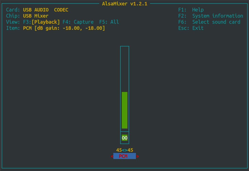
With the up and down arrow keys, the volume can be adjusted and the changes are immediately applied to the audio output.
Attention If you have connected more than one audio card to the Moducop, you can use the left and right arrow keys to switch between the different cards.
Alsa State
The settings defined in alsamixer is stored in the file /etc/alsa/asound.state. This file is automatically loaded by the alsa-state daemon at startup.
Binary Outputs
The IOU06 has two binary outputs. The outputs are low side switching, so the load shall be connected to the positive supply voltage. The outputs are galvanically isolated from the rest of the IO-Module.
Features
The IOU06 has a binary output function block providing:
- 2 galvanically isolated channels from the rest of the IOU6-Module.
- Each pin can be only used as a binary output.
- Supply voltage of both channels may be between 12VDC and 36VDC.
- Switching capability of each pin is 100mA
- Overcurrent/Overload protection
Typical Connection Examples

Using the io4edge API to access the Binary I/Os
First, install the io4edge client library.
Want to have a quick look to the examples? See our Github repository.
First, install the io4edge client library.
Want to have a quick look to the examples? See our Github repository.
Connect to the binary I/O function
To access the binary I/Os, create a Client and save it to the variable c. Pass as address either a service address or an ip address with port. Examples:
- As a service address:
S101-IOU06-USB-EXT-1-binio - As an IP/Port:
192.168.201.1:10000
We need this client variable for all further access methods.
import (
	"os"
	"time"

	log "github.com/sirupsen/logrus"
	binio "github.com/ci4rail/io4edge-client-go/binaryiotypeb"
)

func main() {
	c, err = binio.NewClientFromUniversalAddress(address, timeout)
	if err != nil {
		log.Fatalf("Failed to create binio client: %v\n", err
	}
}
To access the binary I/Os, create a Client and save it to the variable binio_client. Pass as address either a service address or an ip address with port. Examples:
- As a service address:
S101-IOU06-USB-EXT-1-binio - As an IP/Port:
192.168.201.1:10000
We need this client variable for all further access methods.
import io4edge_client.binaryiotypeb as binio
import io4edge_client.functionblock as fb

def main():
  binio_client = binio.Client(address)
Controlling Output Values
The API provides two methods to control channel output values
- Control a single pin
- Control multiple pins
Control a single pin:
    // Turn first channel on
    err = c.SetOutput(0, true)
    // Turn first channel off
    err = c.SetOutput(0, false)
Control multiple pins using a bit mask. The second parameter to SetAllOutputs is a mask that specifies which channels are affected:
    // Turn first channel on, and turn the second channel off
    err := c.SetAllOutputs(0x1, 0x3)
The SetOuput and SetAllOutputs methods return an error if the channel number is out of range
Control a single pin:
    # Turn first channel on
    binio_client.set_output(0, True)
    # Turn first channel off
    binio_client.set_output(1, False)
Control multiple pins using a bit mask. The second parameter to set_all_outputs is a mask that specifies which channels are affected:
    # Turn first channel on, and turn the second channel off
    binio_client.set_all_outputs(0x1, 0x3)
The set_output and set_all_outputs methods raise a RuntimeError if the channel number is out of range
Overcurrent and Overload Handling
The Binary outputs are overcurrent and overload protected. In case an overcurrent condition is detected on one channel, the channel is disabled. To recover from the situation, remove the load completely to allow a relaxing time for the IOU06 to function again.