Installation Guide
This section guides you through the process of installation planning and execution.
Installation to Wall
Make sure, you are using the correct accessory for wall mounting depending on your ModuCop configuration. For example, a 6-slot ModuCop must be mounted with the corresponding 6-slot wall mount brackets.
Accessories for wall and rack mounting are identical and differ only in the position to be fixed at ModuCop
- S104-ACS03-: Wall/Rack mount brackets 4 slot
- S104-ACS04-: Wall/Rack mount brackets 6 slot
- S104-ACS05-: Wall/Rack mount brackets 12 slot
For guidance on mounting orientation, angles, keep free areas, please refer to Installation Requirements.
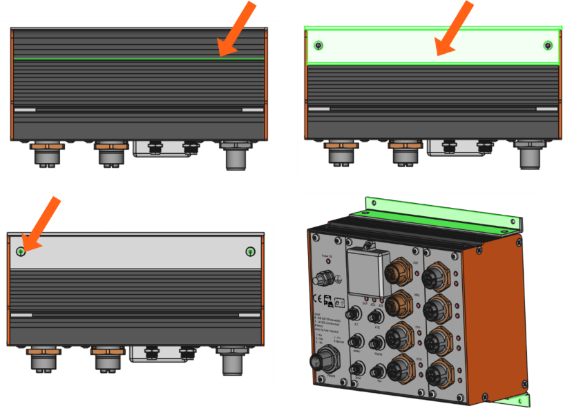
Assembly of Mounting Brackets
- Make sure, threaded bars are properly positioned as shown in the figure below
- Place brackets as shown
-
Fix brackets with two screws M2.5x25 (part of mounting kit) to the threaded bar.
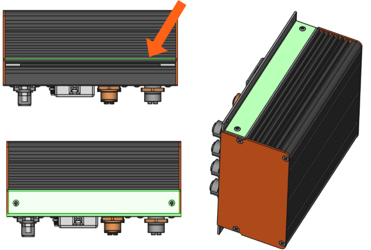
Assembly of ModuCop to Wall
- Select clean and level ground.
- Per mounting bracket use 2x appropriate screws depending on your underground.
- Start mounting top bracket, then bottom bracket.
Installation to DIN Rail
Make sure, you are using the correct accessory and number for DIN rail mounting depending on your ModuCop configuration.
-
S104-ACS02-: DIN rail mounting kit (contains 2x DIN rail holders)
- Use 1 mounting kit for ModuCop configurations of 3 to 6 slot width.
- Use 2 mounting kits for ModuCop configurations above 6 slots width.
For guidance on mounting orientation, angles, keep free areas, please refer to Installation Requirements.
Assembly of DIN Rail Holder
- Make sure, threaded bars are properly positioned as shown in the figure below
- Place holder as shown
-
Use 2x screw M2.5x8 plus lock washer M2.5 (part of mounting kit) per holder to fix holder to threaded bar as shown in the following figure
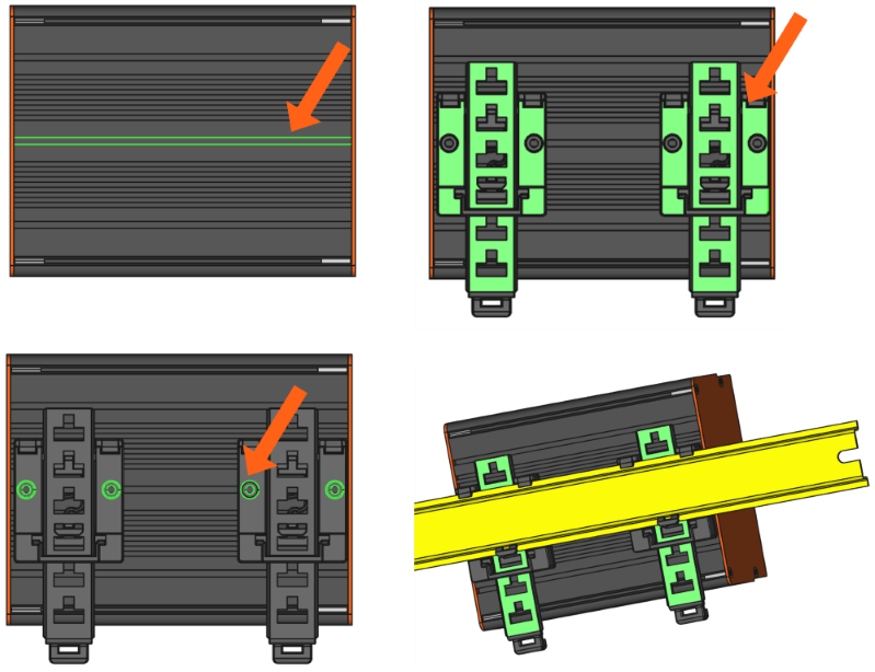
Assembly of ModuCop to 35 mm DIN Rail
- Place the edge computer at an angle of approx. 10° upwards onto the upper edge of the DIN rail.
- Press the device down slightly and snap it over the lower edge of the DIN rail.
Removal of ModuCop from 35 mm DIN Rail
- Pull down flexible flanges of DIN rail holders (e.g. with screwdriver) simultaneously, turn ModuCop slightly upwards from bottom side and remove it upwards.
Installation to 19’’ Sub-Rack
Make sure, you are using the correct accessory for rack mounting depending on your ModuCop configuration. For example, a 6 slot ModuCop must be mounted with 6 slot rack mount brackets.
Accessories for wall and rack mounting are identical and differ only in the position to be fixed at ModuCop
- S104-ACS03-: Wall/Rack mount brackets 4 slot
- S104-ACS04-: Wall/Rack mount brackets 6 slot
- S104-ACS05-: Wall/Rack mount brackets 12 slot
For details please refer to Installation Requirements.
Assembly of Mounting Brackets
- Make sure, threaded bars are properly positioned as shown in the figure below
- Place brackets as shown
-
Fix brackets with two screws M2.5x25 (part of mounting kit) to the threaded bar.
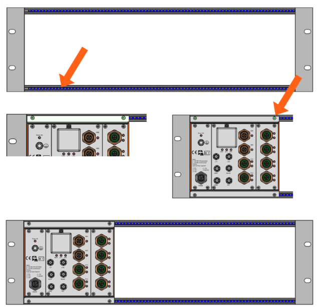
Assembly of ModuCop into 19’’ Sub-Rack
- Check 19’’ sub-rack for fitting threaded bars.
- Use M2.5x6 screws per mounting bracket
-
Start mounting top bracket, then bottom bracket.