Connecting & Powering
In this section you will connect your ModuCop to the power supply and all relevant interface connections asuming you use the ACS01 Starter kit. Otherwise you will need the accessories described here.
Connections
Notice
- The earth connection has to be made first and disconnected last.
- The last connection made is the power wiring.
- Connect the protective earth stud bolt with your earthing system.
- Connect the LTE antenna with the “LTE1” connector.
- Connect the Wi-Fi antenna with the “WLAN1” connector.
- Connect the GPS antenna with the “GNSS” connector.
- Connect the Ethernet cable with the “Ethernet 1” connector.
- Connect the DC power supply cable (M12 connector) with ModuCop’s power input.
Notice In case you don’t use the power cable of the Starter kit, please refer to the user manual for the pinning of the Power Input.

Powering
- Connect the AC power supply with your main supply.
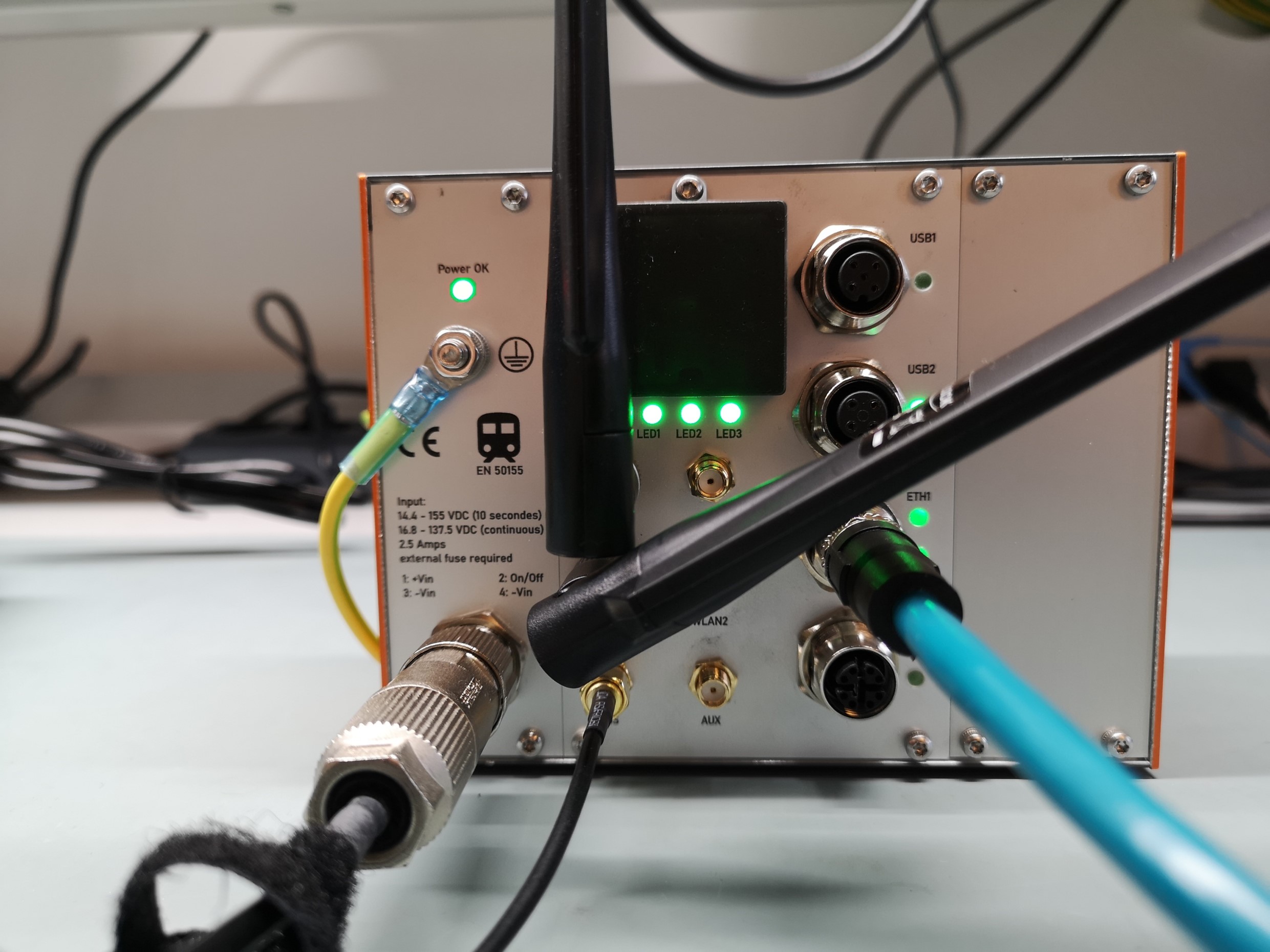
- The indicator LED “Power OK” lights up indicating ModuCop’s internal power supply is stable.
- Your connected and powered ModuCop should look like in the picture below.
Achievements in this Section
Great! ModuCop is now properly connected and powered. Now you can begin establishing the communication.